Mastering the Corner Radius (R-Angle) in Square and Rectangular Hollow Sections
- Share
- Issue Time
- Mar 11,2026
Summary
This guide explores the critical R-angle requirements for hollow sections across global standards like GB/T 6728, ASTM A500, and EN 10219.
Understanding the hollow section R angle is vital for structural integrity. For high-strength Q355B low-alloy steel, R-values typically range from 2.5t to 4.0t, while standard Q235 carbon steel maintains a sharper 1.0t to 3.5t profile. Learn how to calculate, measure, and verify the perfect corner radius for your next engineering project.
Mastering the Corner Radius (R-Angle) in Square and Rectangular Hollow Sections
When we talk about square and rectangular hollow sections (SHS/RHS), everyone focuses on wall thickness and steel grade. But in the real world of fabrication, the Corner Radius—or the R-Angle—is what actually determines if a pipe is "good" or "trouble."
The R-angle isn't just a cosmetic curve; it’s a technical pivot point that affects everything from structural load-bearing to whether your weld is going to crack under pressure. If you are handling Q355B or ASTM A500 specs, understanding the logic behind the R-angle is the best way to avoid rejection during inspection.

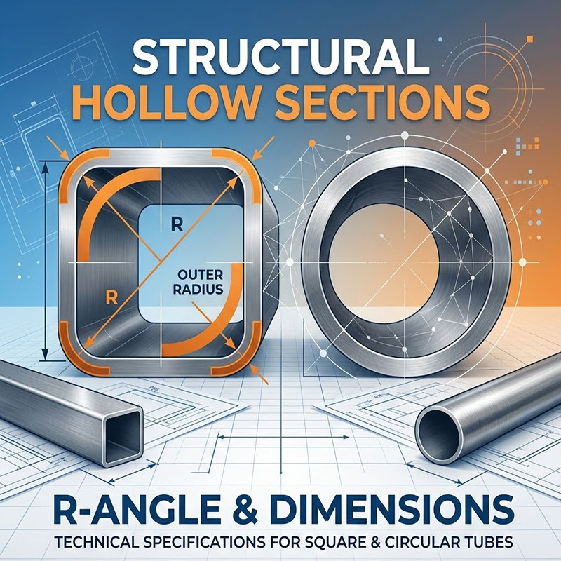
What Exactly is the R-Angle?
In simple terms, the R-angle is the radius of the arc at the four corners of the tube. In a Mill Test Certificate (MTC), we look at two specific measurements:
●External Radius (Ro): The curve on the outside of the pipe (the one most people care about).
●Internal Radius (Ri): The curve on the inside wall. Typically, Ri = Ro - wall thickness (t).
The consistency of these four corners tells you a lot about the mill's quality. If the R-angles are uneven, the pipe will have internal "twist" stresses that make it a nightmare to align during assembly.
How Do We Calculate It?
Every mill has its own secret sauce for roller settings, but the industry generally follows a "rule of thumb" based on the wall thickness (t):
●Standard Cold-Forming: R ≈ 1.5t to 3.0t.
●Blank Width Calculation: If you’re trying to figure out how wide your steel strip needs to be before it hits the forming rollers, engineers use this logic:
L = 2(H + W) - 8R + 2πR
(Where H is Height, W is Width, and R is the Mean Radius).
Measuring in the Field (The "No-Guessing" Way)
You can't just eyeball a radius on a job site. To get it right, we use three main tools:
1.Radius Gauges (R-Gauges): This is the old-school, "no-fail" method. You take a set of metal templates, press them against the corner, and check for light gaps. If it fits flush, it’s a pass.

2.Digital Caliper Indirect Method: We measure the distance from the tangent point to the imaginary sharp corner and use geometric modeling to reverse-calculate the radius.
3.Optical Comparators: For high-end export projects (like LSAW pipes), we take a cross-section slice and put it under a digital projector. The software automatically captures the arc and spits out the exact radius.
What Happens if the R-Angle is "Off"?
When the R-Angle is Too Small (Sharp Corners):
●The Problem: The steel has been "punished" during cold-forming. Sharp corners mean high Stress Concentration.
●The Risk: You’re looking at micro-cracks in the corners and a serious drop in ductility. If the structure vibrates or takes a sudden load, those sharp corners are where it’s going to fail first.
When the R-Angle is Too Large (Rounded Corners):
●The Problem: You’re losing "flat" surface area on the sides of the pipe.
●The Risk: A big round corner looks fine, but it actually reduces the Section Modulus. In plain English: the pipe is slightly weaker against bending. It also leaves big gaps when you try to weld it flush to a flat plate.
Both overly large and overly small corner radii can have negative effects. Pursuing an extremely small R angle is unnecessary; a properly sized corner radius ensures better product performance and stability.

International Standards: A Quick Cheat Sheet
| Standard | Material/Process | Materials/Strength | Requirement (External Ro) |
| GB/T 6728 | Cold-formed | (≤320MPa) | t≤3mm: 1.0t ~2.5t;
3mm<t≤6mm:1.5t ~ 2.5t
6mm<t≤10mm:2.0t ~ 3.0t
t >10mm: 2.0t ~ 3.5t |
| (>320MPa) | t≤3mm: 1.5t ~2.5t;
3mm<t≤6mm:2.0t ~ 3.0t
6mm<t≤10mm:2.0t ~ 3.5t
t >10mm: 2.5t ~ 4.0t | ||
| EN 10219 | Cold-formed Welded | - | t ≤6mm: 1.6t ~ 2.4t;
6mm<t≤10mm:2.0t ~ 3.0t
t ≥10mm: 2.4t ~ 3.6t |
EN 10210 | Hot-finished Welded | - | Maximum 3.0t is the standard ceiling |
ASTM A500 | Structural Tubing | - | Maximum 3.0t is the standard ceiling |
JIS G3466 | Cold-formed Welded | - | Maximum 3.0t is the standard ceiling |
Note: In most international standards such as EN 10219, EN 10210, ASTM A500, and JIS G3466, only the maximum outside corner radius is specified, typically not exceeding three times the wall thickness (3t). The actual radius produced by manufacturers may vary depending on forming processes and material strength.

Can You Fix a Bad R-Angle?
If the pipe comes off the line and the R-angle is out of spec, you have a few levers to pull:
●Sizing Mill Tweaks: The sizing stands at the end of the line are your last chance. Increasing the pressure on the final rollers can "sharpen" an R-angle that's too lazy.
●Induction Heating: For high-strength steel like Q355B, we can use localized heat at the corners during forming. This lowers the resistance and lets us get a tighter, more precise R-angle without the steel cracking.
The R-angle is the bridge between a pipe that looks like a square and a pipe that actually performs like a structural member. Whether you are aiming for the tight specs of EN 10219 or the versatility of ASTM A500, keeping that radius under control is non-negotiable for a quality build.