What Is Pipe Welding?
- Share
- publisher
- Tianjin Yuantai Derun Steel Pipe Group
- Issue Time
- May 13,2024
Summary
Pipe welding, which is a highly practical and universal technology, is concerned with the connection and shaping of pipes.
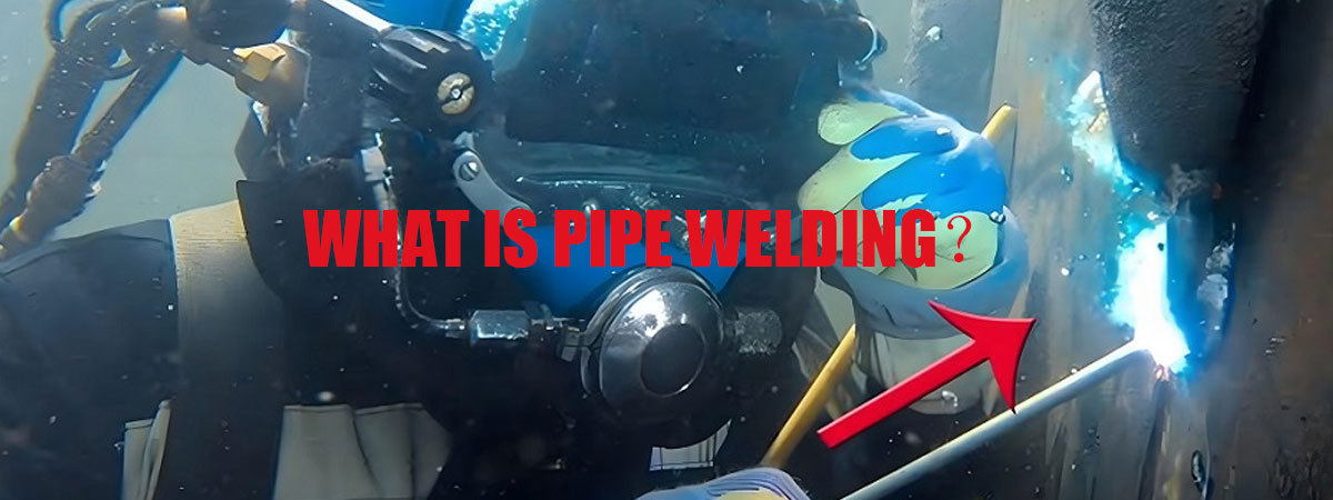
Pipe welding, which is a highly practical and universal technology, is concerned with the connection and shaping of pipes. For you, in-depth study and mastery of this technology, to ensure the smooth construction of every pipeline project has immeasurable significance. Now, let me take you fully into the world of pipe welding, together to explore the mystery of knowledge.
What Is Pipe Welding?
Pipe welding is a method of joining two ends of a pipe together by welding. It is one of the most common connection methods in the piping industry, and its advantages lie in the high strength of welding, good sealing, strong corrosion resistance and so on.
1. Preparation Before Pipe Welding
1.1 Welding Raw Materials
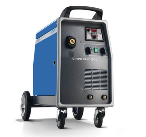
Welding Power Supplies
First and foremost, the welding power source is essential, providing the electrical energy needed for welding.
Welding power supply is the core equipment for welding. Currently on the market there are mainly DC, AC, pulse power and other types of welding power supply. Which type of welding power supply to choose should be determined according to the actual welding situation. Usually, for some smaller pipes, the use of DC welding can be. For some thicker pipes, AC electric welding or pulse power supply is needed for welding.
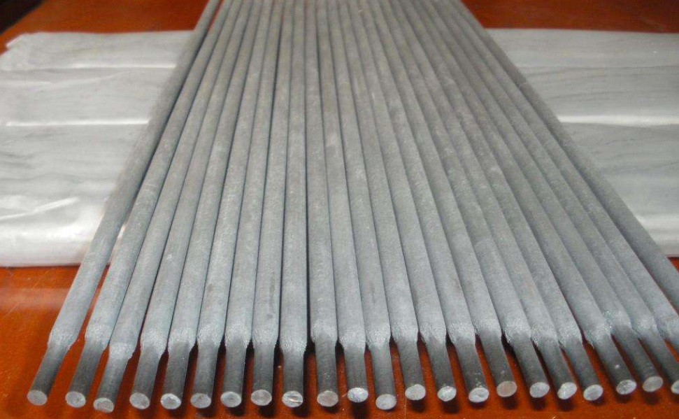
Welding Rod
Welding rods are strips of metal that are melted and filled into the joints of welded workpieces during gas or electric welding. The material of the electrode is usually the same as that of the workpiece. A welding rod is a molten electrode coated with flux for electrode arc welding, which consists of two parts: the flux and the core.
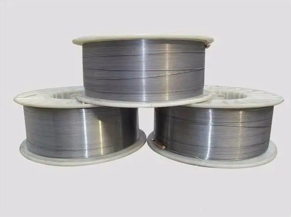
Welding Wire
There are various types of commonly used welding wires such as aluminum neodymium oxide, aluminum zirconium oxide, aluminum barium oxide and pure magnesium. Among them, aluminum neodymium oxide wire is one of the more widely used wires.
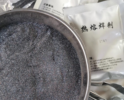
Welding Flux
Welding flux, also called brazing flux, is broadly defined to include molten salts, organics, reactive gases, metal vapors, etc., i.e., removing the base material and brazing material, and generally referring to all substances used to reduce the interfacial tension between the base material and the brazing material in a third way.
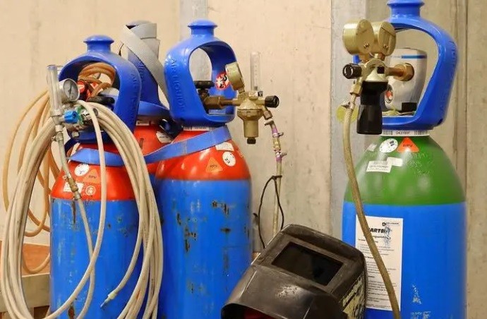
Gas
Pipe welding also requires the use of shielding gas, which is usually an inert gas such as argon, alkane, etc. Protective gas can protect the molten pool and welding area, prevent the weld from being oxidized by air, and thus ensure the quality of the weld.
1.2 Polarity Selection

Positive connection: The welding piece is connected to the positive pole of the power supply, and the welding rod is connected to the negative pole of the power supply.
Reverse connection: the weldment is connected to the negative pole of the power supply, and the electrode is connected to the positive pole of the power supply.
Principle of polarity selection:
Alkaline electrodes often use DC reverse connection, otherwise, the arc burning instability, serious spattering, noise.
Acidic electrodes usually use DC positive connection when using DC power supply.
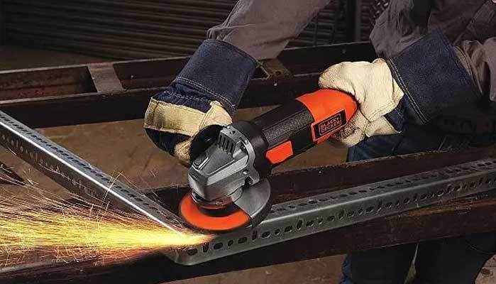
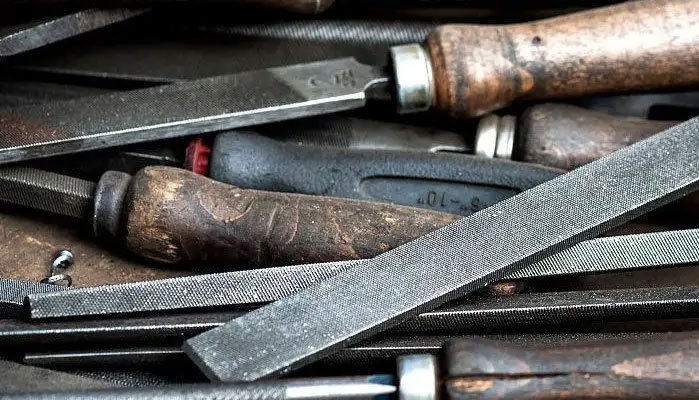
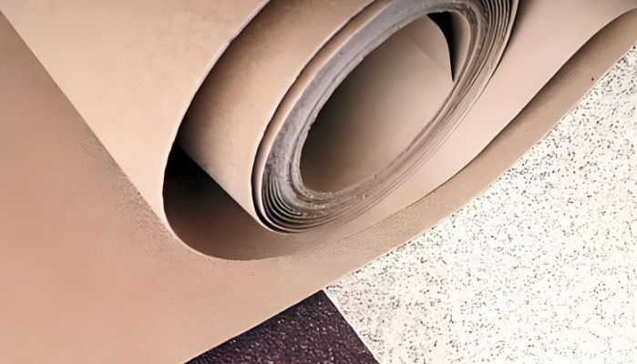
1.3 Grinding Tools
Grinding tools are an essential tool in pipeline welding. After welding, it is necessary to polish the welding seam to make the seam smooth. This can improve the aesthetics of the pipeline and the flatness of the welds. Common grinding tools include angle grinders, files, sandpaper, etc.
Three pictures, including an angle grinder, a file, and sandpaper.
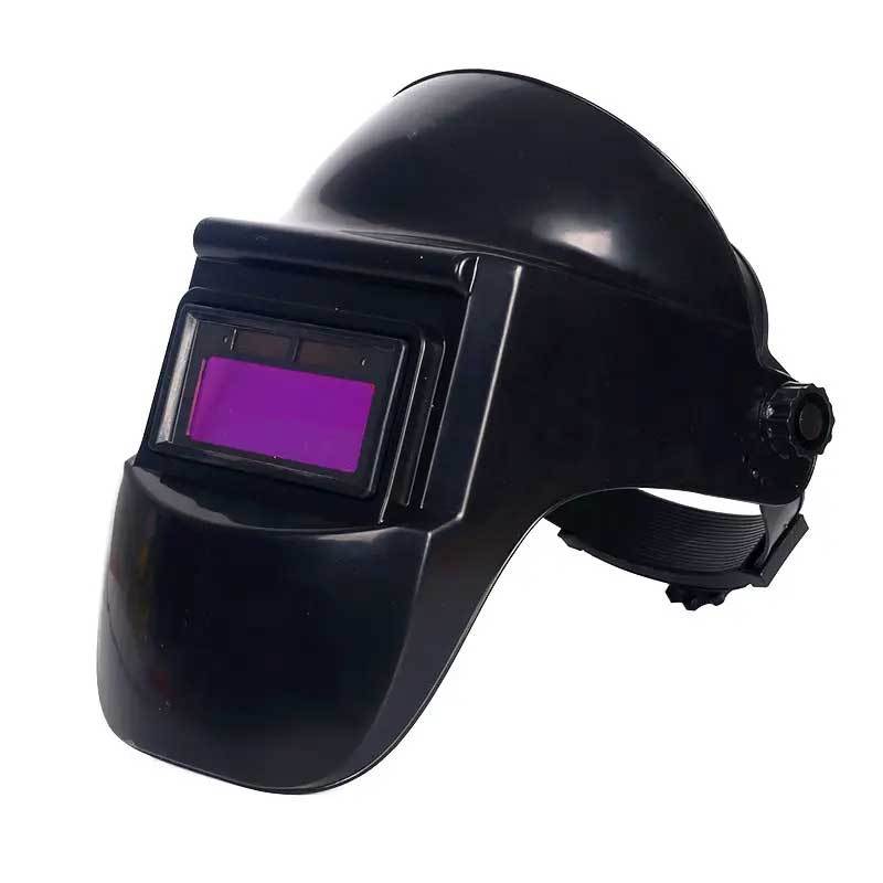
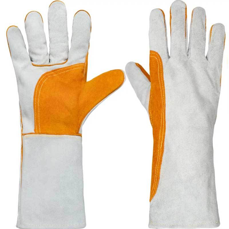
1.4 Protective Tools
Welding pipes is a job that requires skills and is full of danger. You must prepare and wear protective clothing, gloves, face shields, shoes, and so on for welding.
There are 4 pictures, including protective masks, protective shoes, protective gloves, and protective clothing.


2.Type Of Pipe Welding
2.1 Shielded Metal Arc Welding (SMAW)
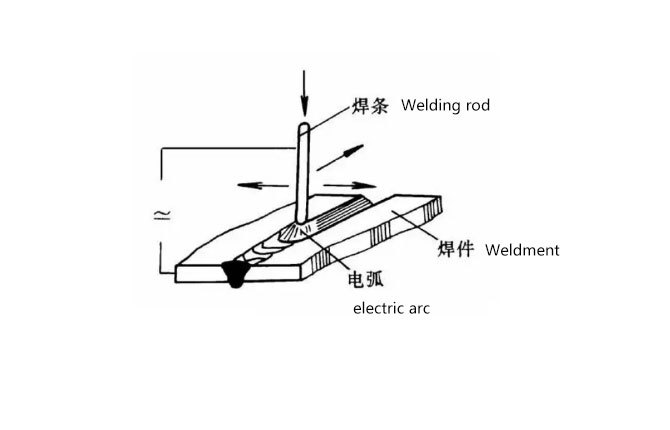
Shielded Metal Arc Welding Meaning
A manual welding method that uses an arc as a heat source to melt the welding rod and base material to form a weld seam, with an arc temperature of around 6000-8000 ℃. Suitable for welding of ferrous metals and certain non-ferrous metals, with a wide range of applications, especially suitable for short and irregular welds.
Advantages
(1) The process is flexible and adaptable, suitable for welding various materials such as carbon steel, low alloy steel, heat-resistant steel, low-temperature steel, and stainless steel in various positions such as flat, horizontal, vertical, and vertical, as well as in different thicknesses and structural shapes of welded parts.
(2) Compared with gas welding and submerged arc welding, the metallographic structure is fine, the heat affected zone is small, and the joint performance is good.
(3) Easy to control stress and improve deformation through process adjustments such as symmetrical welding.
(4) The equipment is simple and easy to operate.
Disadvantages
(1) High technical requirements for welders. The welder's operation technology and experience directly affect the product quality.
(2) poor labor conditions. Welders at work must be hand and brain, highly concentrated, but also subject to high temperature baking and toxic gases, fumes and metal vapor hazards.
(3) low productivity. Affected by the physical condition of the welder, welding parameters to choose a smaller range, so low productivity.
Application
Welding electrode arc welding is widely used in shipbuilding, boiler and pressure vessel, machinery manufacturing, building structures, chemical equipment and other manufacturing and maintenance industries.
2.2 Gas Metal Arc Welding (GMAW)
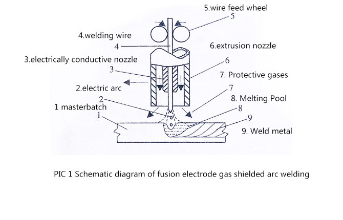
How To Understand GMAW?
Simply put, a piece of melting wire is delivered continuously and at a constant speed to the workpiece to be welded, and then an electric arc (a particularly bright light and heat) is used as a heat source to melt both the wire and the workpiece. In this way, the melted wire and the workpiece are mixed together to form an area of melting called the molten pool, which is then allowed to cool and solidify to form the weld.
To make the weld perfect, we also protect this melted area with a special gas. This gas insulates the surrounding air and prevents it from having a bad effect on the molten metal.
Advantages:
Compared with slag shielded welding methods such as electrode arc welding and submerged arc welding, gas shielded welding has the following advantages in terms of process, productivity, and economic benefits:
(1) Gas shielded welding is a type of open arc welding. The heating and melting of the arc and molten pool during the welding process are clearly visible, making it easy to identify problems and make timely adjustments. Therefore, the welding process and weld quality are easy to control.
(2) Under normal circumstances, gas shielded welding does not require the use of tubular welding wires, so there is no slag during the welding process. After welding, there is no need to clean the slag, saving auxiliary labor hours for cleaning and reducing welding costs.
(3) Widely applicable, high production efficiency, easy to perform full position welding, and achieve mechanization and automation.
Disadvantage
The shortcomings of gas shielded welding with melting electrode include the use of open arc and high current density during welding, as well as strong arc light radiation; Secondly, it is not suitable for welding in windy areas or outdoors; The equipment is quite complex.
Application
Suitable for welding most metals and alloys, most suitable for welding carbon steel and low alloy steel, stainless steel, heat-resistant alloys, aluminum and aluminum alloys, copper and copper alloys, and magnesium alloys.
For high-strength steel, ultra strong aluminum alloys, copper alloys with high zinc content, cast iron, austenitic manganese steel, titanium and titanium alloys, and high melting point metals, gas shielded metal welding requires preheating of the base material and post weld heat treatment, using special welding wires, and controlling the protective gas more strictly than normal.
For low melting point metals such as lead, tin, and zinc, it is not advisable to use gas shielded arc welding. Coated steel plates coated with such metals on the surface are also not suitable for this type of welding method.
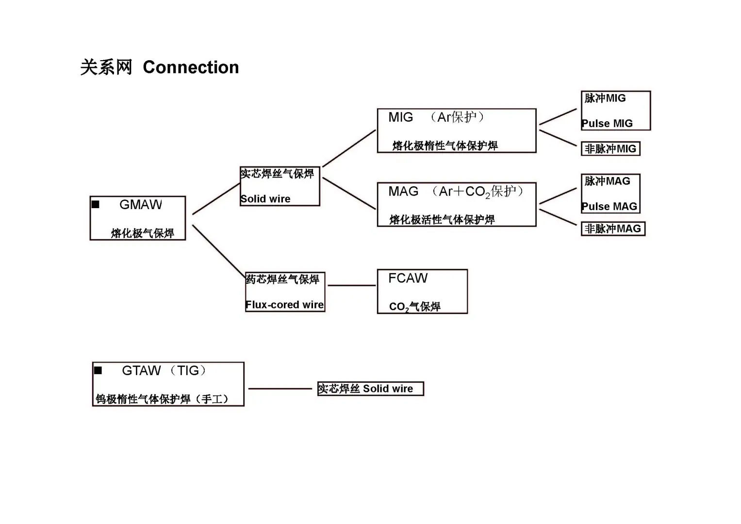
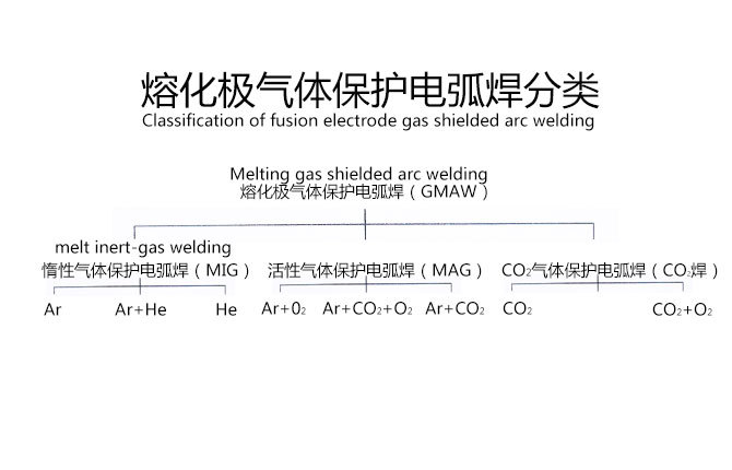
Classification:
Metal inert gas welding can be divided into metal inert gas arc welding (MIG), active gas arc welding (MAG), and carbon dioxide gas arc welding (CO2 welding)
2.2.1 Metal Inert Gas Arc Welding (MIG)
Melting electrode argon arc welding is actually using welding wire as the electrode and melting it. Meanwhile, we use argon gas or a mixture of argon gas and other gases to protect the welding area from external influences. If this protective gas is mainly inert gas Ar or a mixture of Ar and He, then we call it Metal Inert Gas Arc Welding, abbreviated as MIG.
MIG welding is particularly suitable for welding non-ferrous metals such as stainless steel and aluminum and copper. However, if you want to use it to weld low-carbon steel, it may not be as cost-effective as it will be more expensive.
Advantages Of MIG
(1) The shielding gas for MIG welding is a pure inert gas without oxidation, and the arc space has no oxidation, which can avoid oxidation. There is no slag generated during welding, and deoxidizer is not required to be added to the welding wire. Welding can be carried out using welding wires with the same composition as the base metal; Although the shielding gas of MAG welding has oxidizing properties, it is relatively weak.
(2) Compared with CO2 gas shielded arc welding, the melting electrode argon arc welding has stable arc, stable droplet transfer, less welding spatter, and beautiful weld formation.
(3) Compared with TIG welding, melting electrode argon arc welding uses welding wire as the electrode, resulting in high current density of the welding wire and arc, fast melting speed of the welding wire, high deposition rate, large base metal melting depth, small welding deformation, and high welding production.
(4) When MIG welding uses a positive DC arc with welding wire to weld aluminum and aluminum alloys, it has a good cathodic cleaning effect on the oxide film on the surface of the base material.
Disadvantages
(1) Argon and mixed gases are priced higher than CO2 gas, so the welding cost is higher than CO2 gas shielded welding.
(2) MIG welding requires a high level of pre welding cleaning for workpieces and welding wires, which means that the welding process is sensitive to contamination such as oil and rust.
Application Characteristics
It can be used to weld almost any metal material and has a wide range of applications.It is a bit expensive to use this method for low-carbon steel.
2.2.1 MAG active gas shielded arc welding
MAG (Metal Active Gas Arc Welding) is the English abbreviation for Metal Active Gas Arc Welding. It is a mixed gas shielded welding made by mixing a small amount of oxidizing gases (oxygen, carbon dioxide or their mixture) in argon gas. The commonly used gas mixture in China is 80% Ar+20% carbon dioxide. Due to the large proportion of argon in the mixture, it is often referred to as rich argon mixed gas shielded welding.
Advantage
(1) Improve the stability of droplet transition.
(2) Stabilize cathode spots and improve the stability of arc combustion.
(3) Improve the shape and appearance of weld penetration.
(4) Increase the thermal power of the arc.
(5) Control the metallurgical quality of welds and reduce welding defects.
(6) Reduce welding costs.
Disadvantage
Poor gas protection: Active gases (such as carbon dioxide) cannot completely isolate oxygen and water vapor in the air like inert gases, so the weld may have more pores and impurities.
Weld appearance: Compared to MIG welding using inert gas, the weld appearance of MAG welding may be slightly worse and may require more post-treatment.
Arc stability: When using pure carbon dioxide, the arc stability is relatively poor and is prone to splashing.
Application
The process content and selection principles of process parameters for MAG welding are similar to those for MIG welding. Pre weld cleaning is not as strict as the requirements for MIG welding.
MAG welding is mainly suitable for welding black metals such as carbon steel, alloy steel, and stainless steel, especially in the welding of stainless steel, which is widely used.
2.2.2 Carbon Dioxide Gas Shielded Arc Welding
Carbon dioxide gas shielded welding utilizes an arc to generate high temperatures, while preventing air from entering the welding area by adding gas (CO2). This welding method is widely used due to its high efficiency, low cost, and beautiful forming. Next, let's learn about the application and advantages and disadvantages of carbon dioxide gas shielded welding.
Advantage
1. Carbon dioxide gas shielded welding has the advantages of fast welding speed and high efficiency;
2. Carbon dioxide gas shielded welding has a low cost and can be widely applied in fields such as large-scale mechanical production and urban construction;
3. Carbon dioxide gas shielded welding has the characteristics of high welding quality and beautiful welds.
Disadvantage
1. Due to the gas process, laser bending and distortion of laser waves during welding can cause quality fluctuations;
2. Carbon dioxide gas shielded welding has high requirements for welding scenarios and the gas treatment process is relatively complex. Professional operators are required for operation.
Application
Carbon dioxide gas shielded welding can be applied to various types of steel structure welding, such as bridges, automobiles, ships, mining machinery, building structures, oil pipelines, and other fields. During the welding process, gas effectively isolates the welding area from the surrounding air, ensuring the quality of the weld and making it more aesthetically pleasing.
2.3 Flux Cored Wire Arc Welding (FCAW)
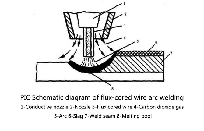
How To Understand FCAW ?
Flux cored wire arc welding is a welding method that uses the arc between the flux cored wire and the workpiece for heating, abbreviated as FCAW in English. Under the action of arc heat, the welding wire metal and the workpiece are melted at the connected parts, forming a molten pool. After the arc moves forward, the tail of the molten pool crystallizes and forms a weld seam.
The Basic Working Principle Of Gas Shielded Welding With Flux Cored Wire
The basic working principle of flux cored wire gas shielded welding is the same as that of ordinary melting electrode gas shielded welding. It uses a meltable flux cored wire as one electrode (usually connected to the positive electrode, i.e. DC reverse connection), and the base material as the other electrode. Pure CO2 or CO2+Ar gas is usually used as the protective gas. The main difference from ordinary gas shielded welding is that the welding wire contains a flux mixture inside. During welding, the melted flux material, wire metal, base metal, and protective gas undergo metallurgical interactions under the heat of the arc, forming a thin layer of liquid slag to coat the droplets and cover the molten pool, providing another layer of protection for the molten metal. In essence, this welding method is a combination of gas and slag protection.
Advantage
Flux cored wire arc welding combines the advantages of manual arc welding and conventional gas shielded welding. Its main advantages are:
(1) Adopting a combination of gas and slag protection, the weld seam is aesthetically pleasing, with good arc stability, minimal splashing, and small particles.
(2) Welding wire deposition speed is fast, deposition efficiency (about 85%~90%) and productivity are high (productivity is 3-5 times higher than manual welding).
(3) Welding various types of steel has strong adaptability, and by adjusting the composition and proportion of the flux, the required chemical composition of the weld metal can be provided.
(4) High welding efficiency (compared to welding rods), suitable for automatic welding, semi-automatic welding or fully automatic welding.
(5) The utilization rate of welding is high (compared to welding rods), and the utilization rate of welding with welding wire far exceeds that of welding rods. Under the same weight, welding wire has a higher cost-effectiveness than welding rods.
Disadvantage
(1) The manufacturing process of welding wire is complex.
(2) Wire feeding is more difficult than solid welding wire, and it is necessary to use wire feeding mechanisms that reduce wire feeding pressure.
(3) The appearance of welding wire is prone to rusting, and the powder is prone to moisture absorption. Therefore, strict management is needed for the storage of welding wire.
Application
Widely used in the production and maintenance of steel products in various fields. Among them, the low dust and high crack resistance sqj501l is suitable for fields such as shipbuilding, steel structures, marine engineering, and mechanical manufacturing
2.4 Submerged Arc Welding (SAW)
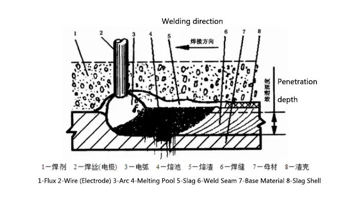
How To Understand SAW?
Submerged arc welding (automatic and semi braking) burns the arc under the flux area, using granular flux as the covering layer of the metal melt pool, isolating air from entering the melt pool. The welding wire is continuously fed into the arc area by the wire feeding mechanism, and the welding direction and movement speed of the arc are completed manually or mechanically.
The Advantages Of Submerged Arc Welding
(1) The welding current used is high, and the corresponding input power is high. Combined with the insulation effect of flux and slag, the thermal efficiency is high and the melting depth is large. The groove of the workpiece can be smaller, reducing the amount of filling metal. Single wire submerged arc welding can penetrate 20mm at a time without beveling the workpiece.
(2) The welding speed is high. Taking the example of butt welding of steel plates with a thickness of 8-10mm, the speed of single wire submerged arc welding can reach 50-80cm/min, while manual arc welding does not exceed 10-13cm/min.
(3) The presence of flux not only separates the contact between molten metal and air, but also slows down the solidification of the molten pool metal. There is a considerable amount of metallurgical reaction time between liquid metal and melted flux, which reduces the possibility of defects such as pores and cracks in the weld seam. Flux can also add some alloying elements to the weld metal, improving its mechanical properties.
(4) When welding in a windy environment, the protection effect of submerged arc welding is better than other arc welding methods.
(5) During automatic welding, the welding parameters can be automatically adjusted to maintain stability. Compared with manual arc welding, the dependence of welding quality on the skill level of welders can be greatly reduced.
(6) There is no arc light radiation, and the working conditions are good.
The Main Drawbacks Of Submerged Arc Welding
(1) Due to the use of granular flux, this welding method is generally only suitable for flat welding positions. Special measures need to be taken for welding in other positions to ensure that the flux can cover the welding area.
(2) It is not possible to directly observe the relative position between the arc and the groove. If an automatic welding seam tracking device is not used, it is easy to weld off center.
(3) The electric field strength of the submerged arc welding arc is relatively high, and the arc is unstable when the current is less than 100A, making it unsuitable for welding thin plates with a thickness of less than 1mm.
Application Of Submerged Arc Welding
Due to its large penetration depth, high productivity, and high degree of mechanization, submerged arc welding is suitable for welding long welds in medium and thick plate structures. It is widely used in manufacturing sectors such as shipbuilding, boilers and pressure vessels, bridges, lifting machinery, railway vehicles, engineering machinery, heavy machinery and metallurgical machinery, nuclear power plant structures, marine structures, etc. It is one of the most commonly used welding methods in welding production today.
In addition to being used for connecting components in metal structures, submerged arc welding can also weld wear-resistant or corrosion-resistant alloy layers on the surface of the base metal. With the development of welding metallurgy technology and welding material production technology, the materials that can be welded by submerged arc welding have evolved from carbon structural steel to low alloy structural steel, stainless steel, heat-resistant steel, and some non-ferrous metals, such as nickel based alloys, titanium alloys, copper alloys, etc.
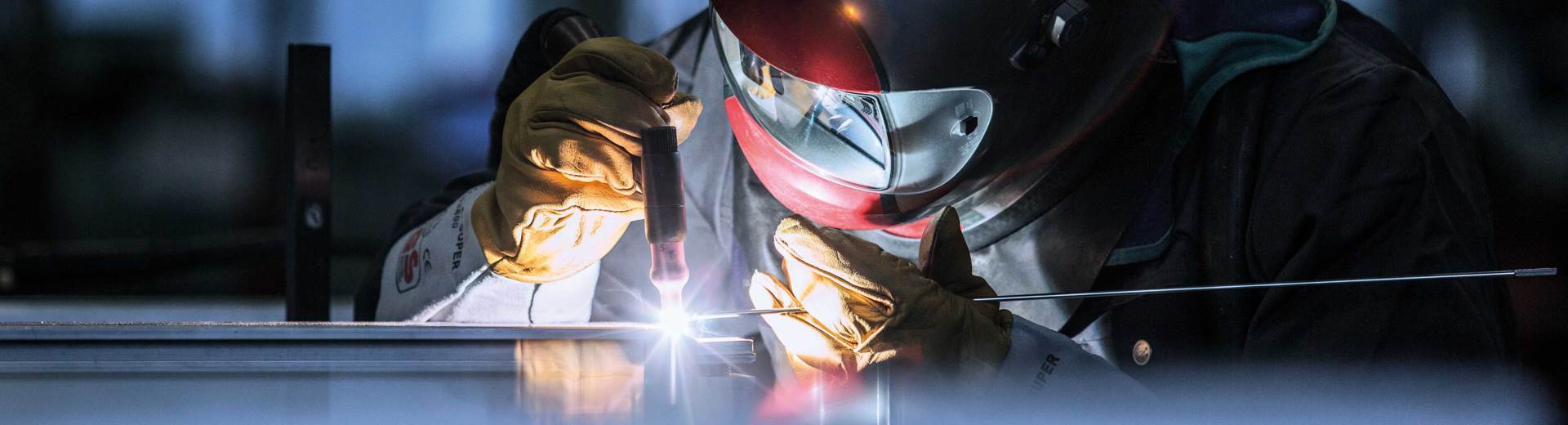
2.5 Tungsten Inert Gas Welding GTAW (TIG)
TIG welding (tungsten inert gas welding) was developed around the mid-20th century. During this process, the electrode is not equivalent to the filler metal, which means that the addition of filler metal (if necessary) can be independently controlled. TIG welding is the only welding method that produces an arc between the electrode and the workpiece to melt the metal.
The welding power supply will generate high-frequency current, which is needed to generate an arc that does not come into contact with the workpiece. This process is usually used for pipe welding applications and is particularly popular due to its ability to perfectly control the weld bead. TIG welding has manual, semi-automatic, or fully automatic versions.
Tungsten Electrode
Tungsten electrode is the core of TIG welding. Tungsten is the element with the highest melting point among all pure metals in the periodic table, with a melting point of 3380 ℃. This means that the tungsten needle will not melt itself when it generates an arc to heat and melt the material. Tungsten electrodes are made by sintering process and formed into tungsten alloys by adding oxidants to improve performance. Depending on the element, the end of the tungsten electrode is marked with different colors.
Pure tungsten (WP) (green)/Smooth, spherical needle/Difficult to arc in DC mode/Poor current carrying capacity
Thorium tungsten (WS2) (blue)/Suitable for all materials/Good arcing performance/Longer service life than WT (thorium tungsten electrode) or WC (cerium tungsten electrode) Cerium tungsten (WC20) (gray)/Suitable for all materials/Good arcing performance
Lanthanum tungsten (WL20) (blue)/Longer service life than thorium tungsten or cerium tungsten/Poor arcing performance
Advantage
>No splashing
>Radiographic testing
>Suitable for all position welding
>The welding seam is aesthetically pleasing and of high quality
Disadvantages
>Relying on welding skills of welders
>Slow welding speed
>The pre welding preparation work requires high requirements, and the rust on the surface of the weld must be completely removed
>Not suitable for thick plate welding
Application
Due to the aforementioned advantages, TIG welding has a wide range of applications in industry and daily life. TIG welding can be used in the following areas:
>It can weld various metal materials, including carbon steel, stainless steel, aluminum alloy, nickel alloy, copper alloy, titanium alloy, etc.
>It can weld workpieces of various thicknesses, achieving high-quality welding from 0.1mm to 10mm and above.
>It can weld workpieces in various positions, including flat plates, vertical plates, horizontal angles, vertical angles, etc.
>It can be used in various industries and fields, such as aerospace, nuclear energy, automotive manufacturing, shipbuilding, chemical industry, medical equipment, etc.
2.6 High Energy Density Welding (HED)
These special welding techniques are rare due to expensive equipment (millions of euros). There are mainly plasma welding, electron beam welding, and laser welding, which are fast and can weld large thicknesses. Laser welding is popular in the medical and electronic fields, and electron beam welding requires a vacuum chamber and a long installation time.
High energy density fusion welding uses high-energy heating materials to quickly melt and form welds, commonly used in high-precision welding. Pressure welding, on the other hand, involves applying pressure and heat to make the metal surface contact and weld without the need for additional heat sources.
Although both are welding methods, their principles and applications are different, and sometimes they can be combined to strengthen the weld seam.
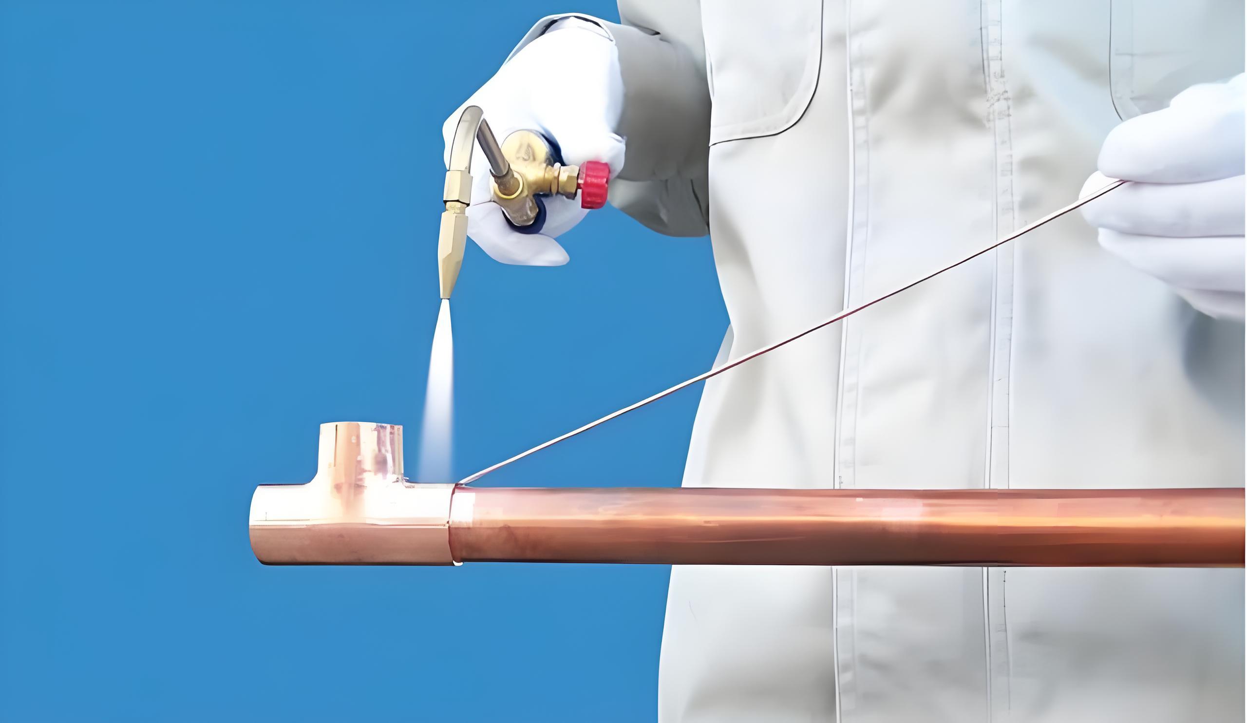
2.7 Brazing
It refers to the welding method of using liquid brazing material to fill the gaps of solid workpieces and connect the metal after heating both the brazing material below the melting point of the workpiece and the workpiece to the melting temperature of the brazing material.
Brazing Type
Soft soldering:The melting point of the brazing material for soft brazing is below 450 ° C, and the joint strength is relatively low (less than 70 MPa).
Soft soldering is commonly used for the welding of conductive, airtight, and watertight devices in the electronics and food industries. Tin lead alloy is the most commonly used solder for soldering.
Hard Brazing:The melting point of the brazing material for brazing is higher than 450 ° C, and the joint strength is higher (greater than 200 MPa).
Hard brazing joints have high strength and some can work at high temperatures. There are various types of brazing materials for brazing, with aluminum, silver, copper, manganese, and nickel based brazing materials being the most widely used.
Advantage
Low heating temperature, smooth and flat joints, minimal changes in microstructure and mechanical properties, and minimal deformation, making it suitable for welding dissimilar metals or materials
Disadvantage
The joint has low strength, poor heat resistance, strict requirements for pre welding cleaning, and the price of brazing materials is relatively expensive
Use
Commonly used for welding thin-walled copper pipes.Brazing is not suitable for welding general steel structures and heavy-duty and dynamic load components. Mainly used for manufacturing precision instruments, electrical components, dissimilar metal components, and complex thin plate structures such as sandwich components, honeycomb structures, etc. It is also commonly used for brazing various types of dissimilar wires and hard alloy cutting tools.
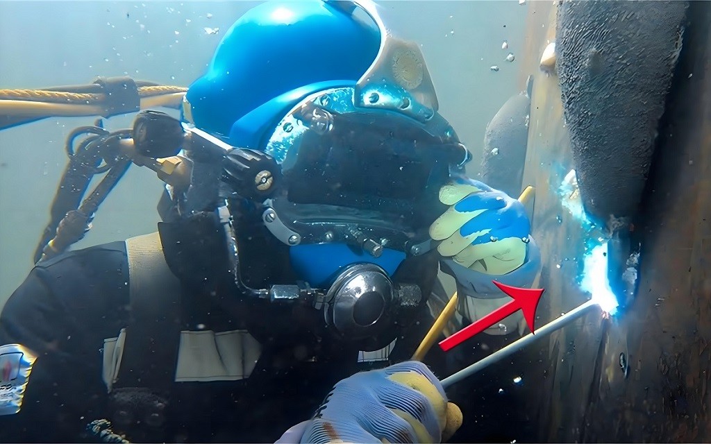
2.8 Underwater Welding
Welding methods performed in water. According to drainage methods, it can be divided into three types: dry, wet, and local dry.
(1) Dry welding
The method of using a large gas chamber to cover the welded part and the welder welding in the gas chamber is adopted.
Welders using inert or semi inert gases in the gas chamber should wear specially designed fire-resistant and high-temperature resistant protective clothing.
Features: Good security, but with significant usage limitations and limited applicability.
(2)Local dry welding
The underwater welding method in which a welder welds in water but artificially discharges the water around the welding area is similar in safety measures to wet welding.
It is still under research, so its use is not yet widespread
(3)Wet welding
Welders perform welding directly underwater, rather than manually draining the water around the welding area.
To overcome the difficulties of arc ignition and stabilization caused by the cooling and pressure effects of water, the arc ignition voltage should be higher than the arc ignition voltage in the atmosphere, and the current should be 15% and 20% higher than the welding current in the atmosphere.
The most applications, but the worst security.
Due to the conductivity of water, preventing electric shock has become one of the main safety issues in wet welding
3. Pipe Welding Steps
Pipe End Cleaning
To ensure good welding quality, it is necessary to clean the surface to be connected first.
Before starting welding, the pipeline must be free of moisture, coatings, rust, oxides, and other pollutants to prevent future defects and expensive repairs. You can use any suitable method for cleaning, such as file, wire brush, grinding, polishing wheel, etc. After cleaning the surface, welding can be prepared.
Align Joints
Aligning the joint is crucial for successful welding. Straight clamps are an ideal choice to ensure alignment of both ends of the pipeline.
When there is no alignment fixture, suitable fixtures can be developed or channel steel/I-beams can be used.
Maintaining appropriate root spacing is also important and should be matched with the filling rod.
When using spacer rings, the distance between the roots should exceed that of the filling rod.
Although this method can fully penetrate the joint, it may be affected by design limitations.
Backing Ring
The backing ring prevents metal splatter from entering the interior of the pipe during welding, ensuring that the weld only penetrates the outer surface. It aids in aligning the pipes, but its use may be limited by design requirements such as smooth fluid flow. When preparing for welding, first install the backing ring, place another pipe on it, secure the backing ring, and spot weld the pipes at four to six points around the circumference.
Backing Gas
During pipe welding, the heated metal tends to react with air, resulting in oxidation and weakening of the weld. Backing gas is used to protect the back side of the weld from contact with the atmosphere. It is commonly used in welding processes such as GTAW and GMAW to ensure welding quality.
Spot Welding
Spot welding connects metal parts using small molten metal beads, similar to how a tailor uses pins to secure fabric pieces before sewing, preparing for the final welding. Its advantages include easy removal, reapplication, and precise alignment. The number of tack welds required varies depending on the diameter of the pipe, and this technique securely fixes the pipe, ensuring its alignment is not affected by root pass shrinkage.
Pipe Welding
Pipe welding, as a highly specialized practical activity, emphasizes the careful selection and preparation of materials, electrodes, and welding parameters.
When starting the welding operation, the first critical initial welding step is the "root pass". Subsequently, the "hot pass" is welded, followed by the filler pass, and finally, the cap pass is completed.
Next, we will delve into a more detailed discussion of each aspect of the welding passes.
Pipe Welding Passes
Pipe welding passes including root passes,hot passes,fill passes,cap passes.
In the process of pipe welding, there are several critical passes that ensure the integrity and strength of the weld. The root pass is the initial layer, laying the foundation for the weld by fusing the base materials together. Following the root pass is the hot pass, which adds depth and stability to the weld by applying higher heat. The fill passes come next, gradually building up the weld until it nears the desired shape and size. Finally, the cap pass seals the weld, providing a smooth and even finish that ensures the structural integrity of the welded pipe.
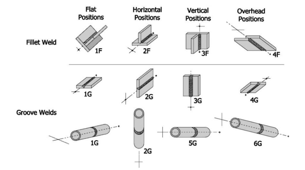
Pipe Welding Positions
The positions for pipeline welding are usually divided into the following types:
Flat welding position (1G): A welding position with a weld seam inclination angle of 0 ° and a weld seam angle of 90 °. At this position, the plate or tube is in a horizontal plane, and the weld metal is deposited above the plate or tube.
Horizontal welding position (2G): A butt joint position with a weld seam inclination angle of 0 ° and a weld seam angle of 0 ° or 180 °. At this position, the plate is in a vertical plane and the weld axis is horizontal; Or the axis of the pipe is vertical, and the axis of the weld seam is in the horizontal plane, so the pipe does not rotate during welding.
Vertical welding position (3G): A welding position with a weld seam inclination angle of 90 ° (vertical upwards) or 270 ° (vertical downwards). The plate is in a vertical plane, and the axis of the weld seam is vertical. During vertical welding, the heat source can be used for welding from bottom to top (upward vertical welding) or from top to bottom (downward vertical welding).
Upward welding position (4G): A welding position where the inclination angle of the butt weld is 0 °, 180 °, and the angle is 270 °. The plate is in a horizontal plane, and the weld metal is deposited from below the plate.
For pipeline welding, there are also the following special positions:
Horizontal fixed welding of pipes (5G): The pipe axis is placed horizontally, and the weld groove is in the vertical plane. The pipe does not rotate during welding.
Pipe fixed welding at a 45 degree angle (6G): The pipe axis is at a 45 degree angle to the horizontal plane, and the pipe does not rotate during welding.
In addition, for pipe plate or pipe corner welds, there are other welding positions, such as 45 degree rotation welding (1F), horizontal welding (2F, pipe axis vertical), pipe axis horizontal (rotation) welding (2FR), overhead welding (4F, pipe axis horizontal fixed), etc.
The selection of these welding positions depends on the specific welding requirements and the structural characteristics of the workpiece.
4. Weld Seam Inspection
How To Test Welds?
Testing pipeline welding is crucial for any welding project to ensure quality and strength. There are two common methods for welding seam testing: non-destructive testing and destructive testing.
Non destructive testing (NDT) is the most commonly used method for welding evaluation. It can evaluate the integrity and size of welds without damaging them.
Radiographic Testing (RT)
Principle: During the process of penetrating matter, rays will interact with the material, reducing its intensity due to absorption and scattering. If there are defects in the local area of the object (specimen) being penetrated, and the attenuation coefficient of the material that constitutes the defect is different from that of the specimen, the intensity of the transmitted rays in that local area will differ from the surrounding area. Place the film in an appropriate position to make it sensitive to light through the action of radiation, and process it in a dark room to obtain the film. The degree of blackening at each point on the film depends on the amount of radiation exposure. Due to the different intensity of projected radiation at the defective and intact parts, there will be differences in blackness at the corresponding parts of the film. The contrast is defined as the difference in blackness between adjacent areas on the film. By placing the film on the viewing light screen and observing through the light, different shapes of images composed of contrast can be seen. Based on this, the film evaluator judges the defect situation and evaluates the quality of the specimen.
Ultrasonic Testing (UT)
Principle: Ultrasonic testing is a non-destructive testing method that uses ultrasonic waves (mechanical waves with a frequency higher than 20kHz) to detect surface and internal defects in materials. Ultrasonic testing of welds is based on the principle that defects in the weld have different acoustic impedances from normal tissue, and sound waves reflect at heterogeneous interfaces with different acoustic impedances to detect defects.
Dye Penetration
Liquid dye penetration testing is a non-destructive testing technique used to inspect finished products and parts for surface damage defects such as cracks, pores, or lack of fusion.
This method utilizes capillary force to suck liquid penetrant into surface discontinuities, making defects visible to the naked eye.
This process can be used for welding and base materials, but is not suitable for high porosity materials.
The dye penetration method helps to identify defects in manufactured parts, which is crucial for ensuring their quality and performance.
Magnetic Particle Testing (MT)
Magnetic particle testing (MPT) uses non-destructive testing techniques to detect surface and subsurface defects in ferromagnetic materials such as iron, steel, and nickel.
To test the material, we magnetize it by applying a magnetic field. Next, we apply a liquid emulsion of magnetic particles onto the surface, which are attracted to any area of magnetic flux leakage caused by material defects, forming visible indications on the surface. We can inspect the images to determine the size, shape, and location of defects.
MPT is commonly used for quality control and inspection in the aerospace, automotive, and construction industries. It can conveniently detect surface fracture cracks in welding, castings, and forgings, as well as fatigue cracks in gears and other components subjected to cyclic loads.
Destructive Testing
Macro Etching Test
Macroetching test is a destructive test to evaluate the quality of welded joints. By taking welding samples and etching with weak acid, the penetration depth, lack of fusion, root penetration, internal pores, or substrate fusion line cracks can be observed. This test can also identify welding issues, such as crack initiation, and reflect the overall quality of production welds.
Corner Weld Fracture Test
Corner weld fracture testing is a method of checking the integrity of welds by gradually applying pressure to a sample welded on one side until it fractures, and then examining its condition after failure to identify defects such as lack of fusion, porosity, and slag inclusion. This type of test can comprehensively evaluate the overall quality of the weld seam, complementing macroscopic etching tests that only observe the cross-section. When combined, it can provide more comprehensive results.
5. Common Problems And Solutions In Pipeline Welding
Welding engineers often encounter unexpected problems during their work, which can be frustrating and costly. The reasons for these problems may be due to poor welding techniques, weak joints, workpiece contamination, substrate dissolution, etc. These problematic pipelines must be reprocessed to ensure safe construction and use of the workpiece pipelines.Now let's take a look at these problems and solutions
5.1 Stoma
Pores are welding defects that occur when nitrogen, oxygen, and hydrogen are absorbed into the welding pool. The weld solidifies and releases this gas, forming tiny cavities within the weld metal.
There are multiple factors that can lead to porosity, such as:
@Moisture or debris on the edge of the board
@Insufficient protective gas
To prevent porosity in the weld seam, welders should:
Using fresh welding materials
Check if there is any leakage from the gas nozzle in the welding gun
Ensure that the edges of the board are clean and dry
In addition, it is important to carefully check the type and flow rate of protective gas and maintain the appropriate angle between the cutting torch and the plate.
5.2 Lack Of Integration
Incomplete fusion during welding may be caused by incomplete root penetration or incomplete root fusion.
When the weld metal fails to reach both sides of the joint, incomplete penetration of the root will occur; When the weld seam is not joined on one side, incomplete fusion at the root will occur.
To address these issues, a wider root gap and larger electrodes are used compared to the gap width size of the welded material.
In addition, using slower travel speeds and weaving techniques between the two boards should help achieve the results you want.
5.3 Mismatch
HiLo, also known as misalignment, is the difference between the internal and/or external heights of two pipeline systems.
This mismatch will have a significant negative impact on the integrity of welded joints - it will weaken the strength of welded joints and make them unable to withstand fatigue over time.
Poor assembly is usually the cause of HiLo; When the fittings welded to the pipeline have different dimensional tolerances, HiLo will occur.
Such problems can lead to defective pipeline systems, which may cause corrosion and pollution due to bacterial colonies and drainage blockages. Larger pipelines (with a diameter of 6 inches or more) are usually more prone to misalignment, and these pipelines may deform during storage or transportation, making them more difficult to install correctly.
Improving pipeline assembly is crucial for reducing HiLo before welding.
5.4 Leakage
When water escapes from the pipeline due to damage or corrosion, leakage occurs. Cracks, holes, or pinholes may cause pipeline leakage. When repairing leaks, make sure to use high-quality materials and the correct techniques.
5.5 Corrosion
Corrosion occurs when metal reacts with oxygen and moisture in the air. This causes rust to form on the surface of the metal. You can remove rust with a wire brush, sandpaper or steel wool. After removing the rust, a coat of paint is recommended to protect the surface.
5.6 Micro movement
Micro motion wear refers to the situation where the ends of two pieces of metal rub against each other, resulting in their wear. Keeping the pipeline clean and dry can prevent this situation.
5.7 Stress Fracture
A stress fracture is a small break in the wall of a pipe that occurs when the pipe is subjected to extreme pressure. Overloading or improper installation can cause cracks in the pipe. Keep pipes at a constant temperature to prevent stress fractures and avoid bending or twisting.
5.8 Pitting Corrosion
Pitting is a type of corrosion that occurs when pitting occurs inside a pipeline. It may be caused by excessive exposure to chemicals in sunlight or water. To prevent pitting corrosion, please avoid direct sunlight on the pipeline and ensure that the water does not contain chlorine or other chemicals.
5.9 Dents
Dents are small indentations that occur on the outside of pipelines. Heavy objects or vehicles may cause dents due to impact or collision. To prevent dents, please drive slowly and avoid colliding with pipes.
Conclusion
Pipe welding uses arc welding to join metal pipes together. This technique is very widely used and pipe welding is one of the practical pipe joining skills. Pipe welders, sometimes referred to as pipe fitters, work in industries such as construction, oil and gas fields, plumbing, manufacturing plants, and power generation. Pipe welding can be a difficult skill and may involve working in uncomfortable or potentially dangerous places, but with the right expertise, safety measures and standards, welding is often preferable to other methods of pipe joining.